

![Linkage [admin] Avatar](http://storage.proboards.com/6710997/images/abWuavvtLTxyaHDIjRCo.png)
Post by Linkage [admin] on Jun 3, 2017 1:24:24 GMT
I rewrote the CNC entirely. Now the code is much cleaner, but there are some quirks anyways.
First of all: No manual controls, just automatic
The machine has capacity for more tools, but they are still not scripted. There's a tool size correction system already there though.
Circles are really messed up, depending on the speed they will actually make a spiral, slightly noticeable at 90º turns though
The servos are made with springs, so there's inertia on play. We don't have reliable, lagless screws so this is the best I had. Also there are lasers that serve as a sort of encoders, so we don't use the input scene.my as output.
The machine is not THAT precise, but it's not like that would be visible in the workpiece. The piece's resolution is 0.05mm, and the machine is made for like 0.01mm (will try to get to ±0.001mm of the target though)
To program it
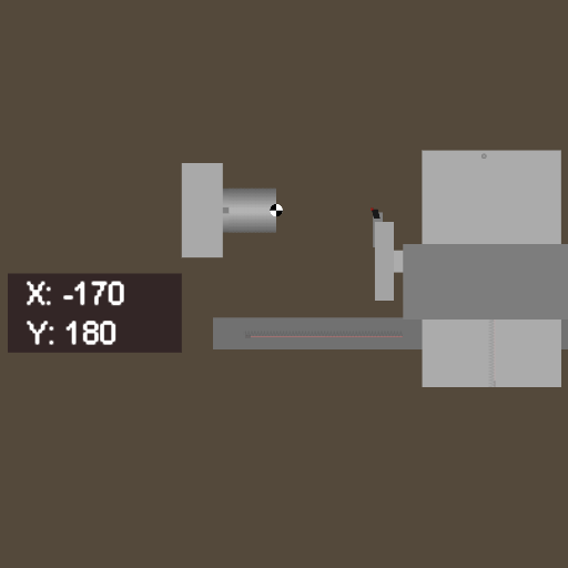
The code is inside the box with coordinates, formatted like this:
__code = [ [instruction 1] , [instruction 2] , ... , [30] ]
The [30] means stop. I'll make it so that the spindle actually regulates the speed later.
Inside each "instruction" block there are 2 or 3 things. They are:
[mode, point, angle]
Angle is not necessary unless you are making circles.
So, mode can be 0(fast movement), 1(line movement), 2(CW circle), and 3(CCW circle). For 0 and 1, you only specify the end point, like:
[0, [-50, 100]]
This would make a fast movement until it gets to that point. The servos will go max speed until they hit the point. The values are in millimeters
For a circle though, the point will be the center, and the angle will be the end angle (from zero to that angle). For example if the tool is at -45º from the center and the angle specified is -90º, it will spin -45º if it's a CW movement, or 315º if it's CCW.
[2, [-30,0], -90]
Angles are in degrees.
The code in the machine is this one, try to understand what the machine does:
[[0, [5, 68]], [1, [-135, 68]], [0, [-70, 68]], [1, [5, 50]], [0, [5, 0]], [2, [-20, 0], -90], [2, [-60, 20], -90], [0, [500, 100]], [30]]
[scene]160605[/scene]
First of all: No manual controls, just automatic
The machine has capacity for more tools, but they are still not scripted. There's a tool size correction system already there though.
Circles are really messed up, depending on the speed they will actually make a spiral, slightly noticeable at 90º turns though
The servos are made with springs, so there's inertia on play. We don't have reliable, lagless screws so this is the best I had. Also there are lasers that serve as a sort of encoders, so we don't use the input scene.my as output.
The machine is not THAT precise, but it's not like that would be visible in the workpiece. The piece's resolution is 0.05mm, and the machine is made for like 0.01mm (will try to get to ±0.001mm of the target though)
To program it
The code is inside the box with coordinates, formatted like this:
__code = [ [instruction 1] , [instruction 2] , ... , [30] ]
The [30] means stop. I'll make it so that the spindle actually regulates the speed later.
Inside each "instruction" block there are 2 or 3 things. They are:
[mode, point, angle]
Angle is not necessary unless you are making circles.
So, mode can be 0(fast movement), 1(line movement), 2(CW circle), and 3(CCW circle). For 0 and 1, you only specify the end point, like:
[0, [-50, 100]]
This would make a fast movement until it gets to that point. The servos will go max speed until they hit the point. The values are in millimeters
For a circle though, the point will be the center, and the angle will be the end angle (from zero to that angle). For example if the tool is at -45º from the center and the angle specified is -90º, it will spin -45º if it's a CW movement, or 315º if it's CCW.
[2, [-30,0], -90]
Angles are in degrees.
The code in the machine is this one, try to understand what the machine does:
[[0, [5, 68]], [1, [-135, 68]], [0, [-70, 68]], [1, [5, 50]], [0, [5, 0]], [2, [-20, 0], -90], [2, [-60, 20], -90], [0, [500, 100]], [30]]
[scene]160605[/scene]